

 English
 中文简体
中文简体 русский
 Español
 عربى
عربى
Submit feedback
Silicone Reducer Coupler Hose: Sizing, Tolerance and Installation Explained
Industry news-Content
- 1 What a Silicone Reducer Coupler Hose Actually Is
- 2 Why Silicone Handles the Transition Zone Better
- 3 Where Reducer Couplers Earn Their Keep
- 4 How to Specify One Correctly
- 5 Installation Details That Decide Whether It Leaks
- 6 Pairing Reducers with Hard Lines and Fittings
- 7 What a Specialized Manufacturer Adds
You have measured the outlet on your radiator at 32 mm and the inlet on your water pump at 28 mm. No amount of clamp tension will make a single-diameter hose seal both ends reliably for long. The silicone reducer coupler hose exists to close exactly this kind of gap, and it is one of the least expensive components in a cooling or boost circuit that still decides whether the whole system holds pressure.
The short version is this: get three things right — the inside diameters at both ends, the reinforcement construction, and the clamp position — and a molded silicone reducer will outlast the rubber hoses around it. The rest of this article explains how to check each of those three things before you buy and again while you install.
What a Silicone Reducer Coupler Hose Actually Is
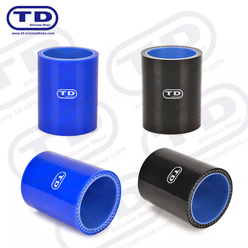
A reducer coupler is a straight silicone hose molded with two different inside diameters, joined by a concentric taper in the middle. One end slides over the larger spigot, the other over the smaller one, and the taper carries the transition smoothly so coolant or charge air does not stall against a sharp internal step. The same logic is available in angled forms, such as 45° and 90° reducer elbows, for circuits where the two connection points are not in line.
Because the transition is molded as one continuous piece of reinforced silicone, there is no glued joint, no separate stepped adapter and no second pair of ends to seal. Fewer joints mean fewer leak paths, which matters most in the corners of an engine bay or a machine frame that you cannot easily inspect once assembly is complete.
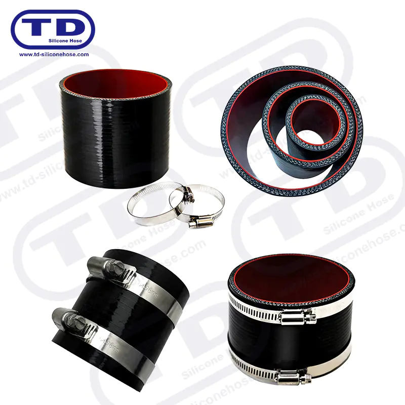
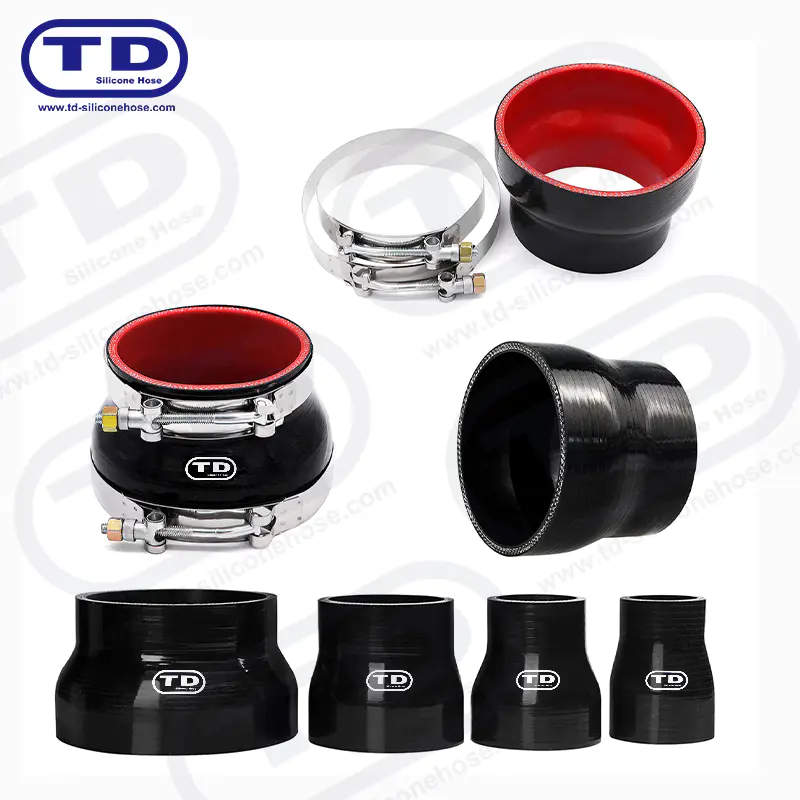 Reinforced Silicone Straight Reducer Hose CouplerThis one-piece molded silicone reducer eliminates glued joints and extra leak paths in hard-to-inspect areas. With 2-6ply polyester reinforcement and -50°C to +250°C rating, it handles the stress and heat cycling described for taper sections.View Product →
Why Silicone Handles the Transition Zone Better
The taper is the most stressed part of any reducer. It sits under clamp load at both ends, flexes with engine movement, and cycles between ambient and full operating temperature every time the machine runs. An inferior material shows its age right here first.
Cured silicone reinforced with polyester fabric keeps its flexibility from roughly -50°C up to about +230°C in continuous service. Common rubber hose compounds start to harden and micro-crack well below that ceiling, usually after prolonged exposure above roughly 120-130°C, and the embrittled wall eventually splits along the clamp line. Silicone also resists the ozone and UV attack that dulls and cracks rubber under the hood, and it holds up against modern glycol-based coolant additive packages without the internal degradation some rubbers suffer.
Construction matters as much as the base material. A standard automotive coupler is built from two to four plies of polyester reinforcement embedded in the silicone wall, which gives a wall thickness of roughly 4.5-5 mm at three plies. That layered wall is what lets the hose hold its shape under clamp load instead of bulging at the taper or collapsing where the diameter steps down.
Where Reducer Couplers Earn Their Keep
Cooling circuits
In radiator and heater circuits, reducers connect a pump inlet to a radiator tank outlet when the two ports are different sizes. That mismatch appears constantly in modified cars and racing builds, where a performance radiator meets original plumbing, and just as often on buses, trucks and motorcycles during replacement work. The reducer lets the upgrade proceed without re-engineering the surrounding pipework.
Charged-air circuits
On turbocharged and supercharged engines, the reducer usually joins the compressor or intercooler outlet to hard piping of a smaller diameter. This location sees hot compressed air and repeated pressure spikes; reinforced charge air cooler hoses are engineered for peaks up to around 10 bar depending on diameter and construction. At pressures like these, clamp selection and spigot engagement stop being optional details.
Industrial machinery
Outside road vehicles, reducers bridge cooling and heating loops on generators, compressors and process equipment, where ports from different equipment generations rarely match. The temperature and pressure logic is identical to automotive use; only the diameters and duty hours change.
How to Specify One Correctly
Before ordering, measure the outside diameter of the pipe at each connection point, because the hose slides over the spigot and its inside diameter must match. A few tenths of a millimetre of tolerance on the hose ID is normal; a full millimetre of gap is not something a clamp should be asked to absorb. If a spec sheet does not state both IDs, the ply count and the taper position, ask for them — those three lines tell you most of what you need to know.
| Specification | What to check | Why it matters |
|---|---|---|
| Inside diameter, both ends | Match each pipe OD; expect roughly ±0.3-0.5 mm tolerance on the hose ID | Wrong ID at either end is the most common cause of blow-off and slow leaks |
| Taper length and position | Confirm the taper is centered and long enough for the diameter step | A short taper creates turbulence and stiffens the transition zone |
| Reinforcement plies | Two to four polyester plies; more plies for pressure duty | Ply count drives pressure rating and stability under clamp load |
| Hardness | Shore A roughly 50-65 for couplers | Too soft deforms under the clamp; too hard resists seating on the spigot |
| Temperature range | Continuous service to about +230°C | The taper sits in one of the hottest, most cycled zones of the circuit |
| Negative pressure | Choose a wire-reinforced wall if the line can see suction | Polyester-only walls can flatten under vacuum conditions |
Three buying mistakes account for most returns and field failures we hear about:
- Ordering by outside diameter instead of inside diameter, which leaves a gap the clamp cannot close evenly.
- Assuming the taper sits at the exact midpoint without checking, which shortens engagement on one end.
- Overlooking vacuum or negative pressure in heater and breather lines, which calls for wire reinforcement rather than a standard wall.
For a deeper walkthrough, our guide on how to select the right silicone reducer coupler hose covers diameter matching and duty matching in detail.
Installation Details That Decide Whether It Leaks
Fit the hose so each end fully covers its spigot — as a working rule, at least the width of the clamp band plus a few millimetres of engagement past the pipe bead. Position each clamp directly over the bead rather than on the plain wall behind it: the bead gives the clamp a shoulder to seat against, while a clamp floating on a smooth section will creep as the silicone softens when hot.
Clamp type follows the duty. T-bolt clamps put even radial load across a wide band and hold their setting through heat cycling, which is why they are the default choice on boost lines and main coolant runs. Spring-reinforced T-bolt versions go a step further and compensate as the hose expands and contracts with temperature. Ordinary worm-drive clamps remain acceptable on low-pressure vacuum and breather lines where loads are light.
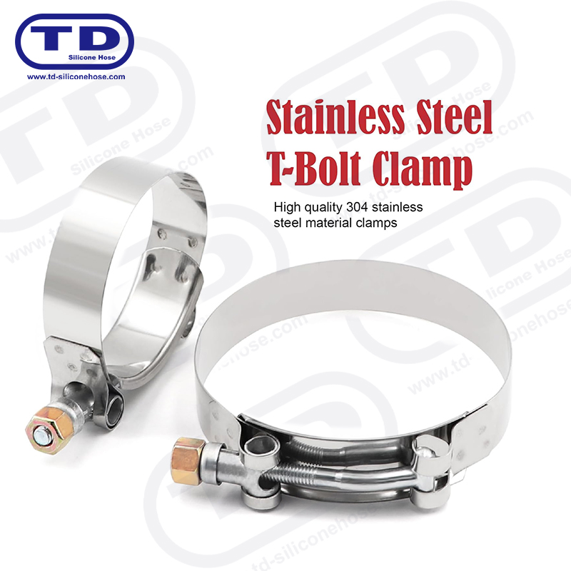 Heavy Duty 304 Stainless Steel T-Bolt Hose ClampMade from SUS 304 stainless steel with a 19mm band, this T-bolt clamp applies even radial load and holds its setting through heat cycles, matching the recommendation to use T-bolt clamps on boost and main coolant lines.View Product →
Torque matters as much as clamp type. Silicone is softer than rubber, so it deforms rather than grips when a clamp is overtightened, and a deformed wall becomes the leak path itself. Tighten to the clamp manufacturer's specified torque, re-check after the first full heat cycle, and inspect band position during scheduled maintenance. For a longer checklist covering cleaning, storage and periodic inspection, see our guide to installing and maintaining silicone reducer coupler hoses.
Pairing Reducers with Hard Lines and Fittings
When one side of the circuit is rigid pipe or a machined housing rather than a hose spigot, the joint is usually finished with an aluminum fitting integrated into the line. A machined aluminum fitting with a rolled or beaded profile gives the silicone end a defined shoulder to clamp against, and the metal's thermal conductivity helps shed heat from the joint area. The measurement discipline is the same as before: confirm the bead diameter against the hose ID first, and order second.
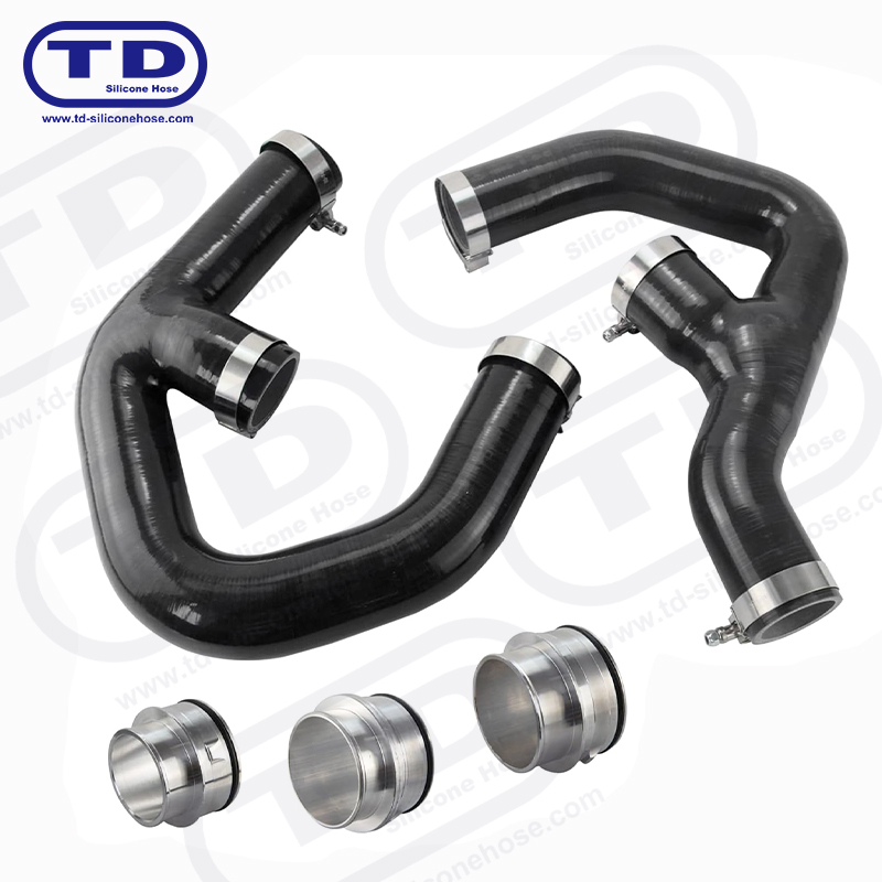 Custom Aluminum Fittings for Silicone HoseMachined aluminum fittings give silicone hose ends a defined beaded shoulder to clamp against and help shed heat from the joint, making them a natural finish for connections between reducers and rigid pipe or housings.View Product →
What a Specialized Manufacturer Adds
Because reducers are molded parts, the tooling decides the taper geometry, wall thickness and surface finish. A specialized silicone hose manufacturer can vary those parameters — a longer taper, an extra ply, a wire helix, a specific hardness — instead of forcing your circuit to fit a catalog part. Our factory in Ningbo produces silicone hoses for the cooling and heating systems of cars, trucks, motorcycles and industrial machinery under an IATF 16949 quality management system, across nine product series and more than 1,500 products, with convenient sea, land and air freight routes for export orders.
That production depth matters most when your requirement sits slightly off-standard: a non-catalog diameter step, a fluorosilicone lining for fuel or solvent contact, or a hose destined for a hydrogen fuel cell cooling loop, where material cleanliness carries its own requirements. A manufacturer who already molds those variants will turn a standard reducer order around faster and with fewer surprises.
A silicone reducer coupler hose looks like the simplest part in the circuit, and that is exactly why it deserves careful specification: nobody notices it until it leaks. Measure both diameters, confirm the construction against the duty, clamp on the bead, and re-torque after the first heat cycle. Do those four things and the reducer will quietly do its job through years of thermal cycling.
Our Product //
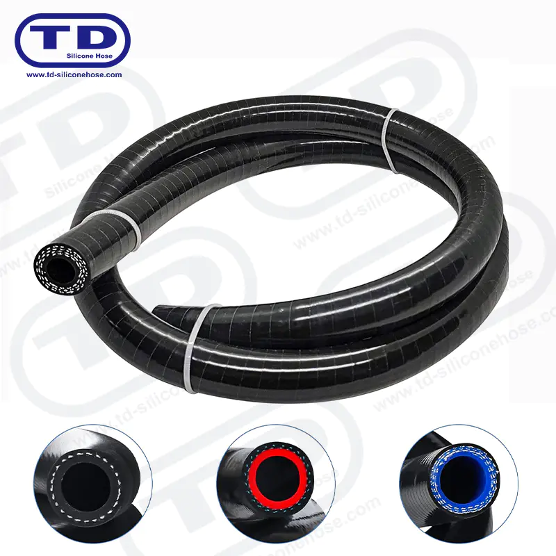
Ningbo Tiandai Auto Parts Co., Ltd. All Rights Reserved. ALL RESERVED.
Wholesale Automotive Silicone Hose Manufacturers
